CASE STUDY · STRUCTURAL BIM · PRE-FEASIBILITY ENGINEERING
A 240 m tower, from BIM model to modal analysis.
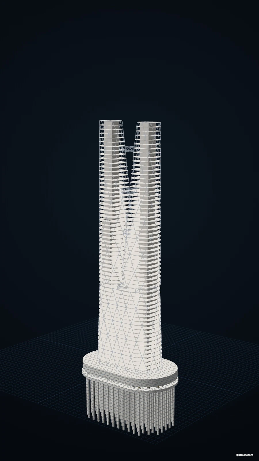
K60 is a KAMON & CO. research project: a conceptual tower on an isolated platform in Medellín. A single Revit model, from form to calculation, with no redrawing between programs.
- HEIGHT
- 240 m · 60 levels
- SYSTEM
- Two concrete cores + CFT diagrid
- ISOLATION
- 123 bearings on 123 Ø 2.0 m piles
- STATUS
- Pre-feasibility engineering
This case study shows the structural BIM modeling and structural analysis workflow KAMON & CO. applied to the K60, a conceptual 240 m tower with seismic base isolation. The model was built in Revit 2026. The analytical model was generated from it without redrawing and calculated in Robot Structural Analysis 2026: modal analysis with fixed and isolated base, finite elements of the isolation platform and floor beams. The output is a set of structural sheets, preliminary sizing drawings and a 3D viewer showing the analysis, the concrete and the reinforcement.
THE CHALLENGE
Isolating a 240 m tower only works if the structure is stiffer than the isolation.
Built base-isolated buildings rarely exceed 150 to 200 m in height. The K60 is framed at that limit: a 72 × 40 m body that, at a third of its height, splits into two arms joined by three bridges, all on a 104 × 64 m platform resting on isolators.
For the isolation to protect the tower, the fixed-base period of the superstructure must stay clearly below the period of the isolated system, close to 5 s. If the tower is flexible, the two periods converge and the isolation stops filtering the earthquake. There were three questions:
- 01How stiff must the cores and the diagrid be for the fixed-base period to stay below about 3 s?
- 02How much does the period lengthen when the tower rests on 123 isolators, and how much mass does the first mode engage?
- 03Does the platform distribute the tower load without any isolator exceeding its working pressure?
THE SCOPE
One model, four deliverables.
- 01
Structural BIM model in Revit 2026
Piles, foundation mat, isolators, platform, columns, two 70 MPa concrete cores, composite slabs, W beams and the CFT tube diagrid, with a custom family for the KA-LRB-1800-HS isolator.
- 02
Analytical model and calculation in Robot Structural Analysis 2026
The analytical model was generated from the BIM model, without redrawing. It includes fixed-base and isolated modal analysis, finite elements of the platform and the level 11 beams.
- 03
Documentation
Preliminary structural drawings (revisions P01 to P03) and presentation sheets in Revit.
- 04
3D viewer
Analysis, concrete and reinforcement, aligned in a single coordinate system.
WHAT THE MODEL CONTAINS
| Element | Quantity |
|---|---|
| Steel members (W beams and CFT diagrid) | 8,093 |
| Concrete columns and piles | 471 |
| Slabs | 102 |
| Core walls | 32 |
| Isolators (parametric family) | 123 |
| Structural elements with geometry | 8,821 |
| Modeled reinforcing bars | 109,771 |
THE PROCESS
From concept to calculation in five steps.
How the K60 structural model was developed
- 01
Preliminary sizing · Judgment before software
Loads under NSR-10, isolation under A.3.8 with ASCE/SEI 7-05, chapter 17, and a first estimate of the fixed-base period. In revision P02 the base CFT diagonals moved to Ø 1.40 m with a 70 mm tube, and the cores of each arm to 0.90 m walls. Stiffness, not strength, governs the sections: the most loaded diagonal works at 39 % of its capacity.
- 02
BIM model · One geometry for everyone
Revit 2026 with levels every 4.0 m, a diagrid in four-level modules, a transfer truss at level 21 and bridges at levels 34, 44 and 54. P03 added a technical sub-basement below level 1 and radial floor beams toward the cores, with a maximum span of 12.7 m at the base.
- 03
Analytical model · No redrawing
The Revit analytical model went to Robot with 4,641 nodes and about 6,640 members. Any geometry change goes back to the calculation from the same model.
- 04
Analysis · Fixed base versus isolated base
Two modal analyses were run, a finite element model of the platform on the 123 isolators, and the calculation of the 184 beams of level 11.
- 05
Documentation and viewer · What is calculated is shown
2D drawings in PDF and DXF, Revit sheets and a web viewer where the deformed shape oscillates with the actual period of each mode.

Pre-feasibility engineering · Revit 2026 + Robot Structural Analysis 2026
@kamonandcoTHE RESULT
The superstructure stays stiff; the isolated system, slow.
With a fixed base, the Robot model gives a fundamental period of 2.98 s in the short direction, right at the target limit. On the 123 isolators, the first mode shifts to:
5.48 s first-mode period with isolated base
In that first mode the tower moves almost as a block on the isolators. It engages 97.1 % of the mass in the short direction (98.8 % in mode 2, in the long direction), against 54.9 % for the same mode with a fixed base. The earthquake concentrates at the isolation plane, not along the height of the tower.
MODAL ANALYSIS
| Result | Fixed base | Isolated base |
|---|---|---|
| Mode 1 (short direction) | T = 2.98 s · 54.9 % of mass | T = 5.48 s · 97.1 % of mass |
| Mode 2 (long direction) | T = 2.41 s · 48.6 % | T = 5.29 s · 98.8 % |
| Mode 3 (torsion) | T = 1.79 s | T = 3.60 s |
| Isolated / fixed period ratio | — | 1.84 |
Isolation platform and typical floor (finite elements, service)
- 01
Platform on 123 isolators
The average service load per isolator is 17,870 kN, 78 % of the 22,900 kN working load. The distribution by position is still being adjusted in the next revision.
- 02
Level 11 beams
184 beams, maximum service deflection of 23.3 mm and maximum ultimate limit state moment of 1,560 kN·m.
WHAT REMAINS TO BE SOLVED
A final design still requires the geotechnical study and site microzonation, a time-history analysis with nonlinear isolators, wind tunnel testing and the isolator manufacturer’s prototype tests.
K60 case study frequently asked questions
Is the K60 a built project?
No. It is a KAMON & CO. conceptual research project at the preliminary sizing stage. It has no client or defined site; the figures are criteria and calculation results with stated assumptions.
Why model in Revit and calculate in Robot Structural Analysis?
Because the analytical model is generated from the BIM model without redrawing. Geometry, sections and materials are the same in both programs, and a design change goes back to the calculation without transcribing data.
What does the fixed-base versus isolated modal analysis show?
That the superstructure is stiff enough to be isolated. With a fixed base the period is 2.98 s and with an isolated base 5.48 s. In the isolated mode the tower moves as a block and engages 97 % of the mass.
Which codes were used?
NSR-10 for loads, seismic hazard and isolation (A.3.8), complemented by ASCE/SEI 7-05, chapter 17, for isolated systems. Hazard and soil are assumptions to be replaced by the microzonation and the geotechnical study.
Does the model include the reinforcement?
Yes. It has 109,771 modeled bars in piles, columns, foundation mat, platform and the slabs of all 60 levels. They can be seen in the viewer’s Rebar layer.
Does this workflow apply to a real project?
Yes. It is the same structural BIM modeling, analysis and documentation workflow KAMON & CO. offers in its services. In a real project, the design and the signing of the drawings belong to the structural engineer of record.
REFERENCES
- AIS (2010). Colombian seismic building code NSR-10, Titles A and B. www.scg.org.co
- ASCE (2006). ASCE/SEI 7-05 Minimum Design Loads for Buildings and Other Structures, chapter 17: Seismic Design Requirements for Seismically Isolated Structures. ascelibrary.org
Does your project need a structural model that can be calculated?
From the BIM model to the analytical model and the drawings, in a single workflow: we apply it to every structural project we support.
Let’s talk about your project See structural BIM design See the K60 in Projects